Related pages
Plans for the extension were revived in the mid-1950s, and the new control room would be equipped with a main switching system allowing 200 sources to be routed to any of 150 destinations and a second system for switching television sound circuits. These systems would use uniselectors - the Siemens Type 1200.
These uniselectors were effectively high speed motorised 16-pole, 52-way switches - 16 wipers tracking round 52 stationary contacts, arranged in a semi-circle, at the rate of 200 contacts per second. Thus the wipers would sweep the entire contact bank in about 1/4 second. Each of the 16 wipers and their associated contacts are collectively known as a 'level'. The pictures below show the front and rear views of some selectors.
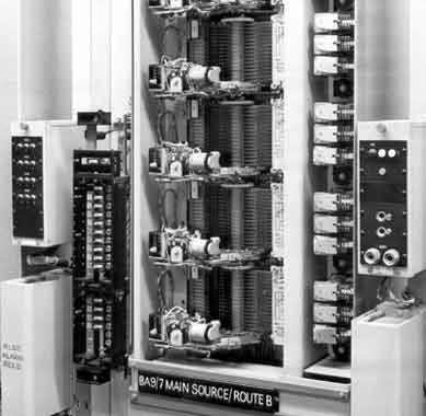
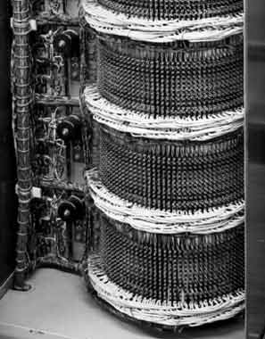
Why sixteen levels? In addition to switching the output of the source to the destination (on levels 1 and 2) there were several other circuits to be switched. The 'cue line' on levels 3 and 4, from destination back to source, gave a means of sending programme for cueing purposes and the 'control line' on levels 5 and 6 provided two-way telephone communication. Switching associated with the control line used 7 and 8 and Level 9 was spare. 10 to 12 provided remote control of tape machines, level 12 could alternatively carry studio red light signalling. Levels 13 and 14 were used to operate indicator lamps which showed which source was selected to a given destination and, as mentioned above, levels 15 and 16 were used in the operation of the uniselectors themselves.
Each destination had its own set of three uniselectors. The first two, A and B, each had the full sixteen levels but the sources on the C and D codes didn't have all the facilities described above, and could thus share a selector. This C/D selector was constructed so that the wipers associated with the C sources were at 180 degrees to the wipers of the D sources.
Let's look at how a single selector could be controlled so that it stopped at the required source.
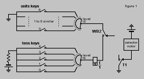
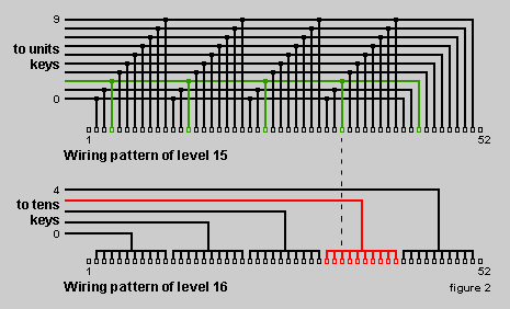
When the operate key (not shown here) was pressed the relay WB operated, closing the contacts WB2, and the selector began to motor. When the wipers of levels 15 and 16 reached the required source, as indicated by the hatched line, the circuit with the relay T was completed, the relay operated and the selector stopped.
Here is a simplified version of the circuit that was used in BH:
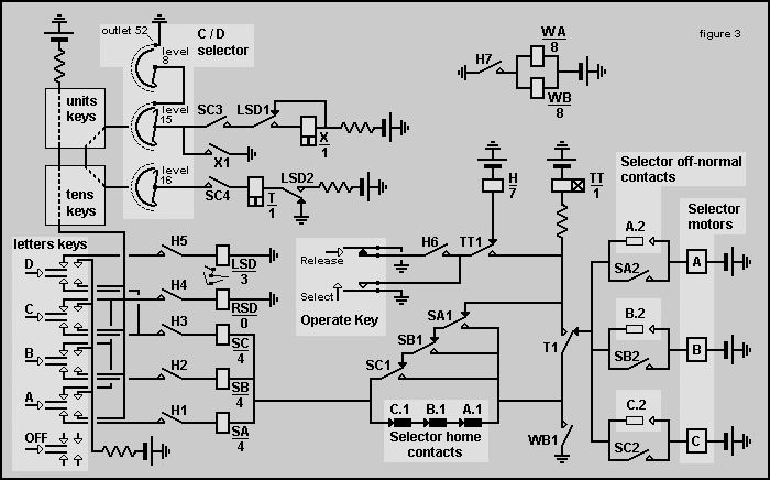
Let's assume that an 'A' selection has been made. SA/4 operates via H1, the home contacts of all three selectors (C.1, B.1 and A.1) and WB1 to earth. At this point the A selector would motor via SA2, T1 and WB1. The selector A1 home contacts open as soon as the selector operates, but SA/4 is self held via SA1 and WB1.
The selector would motor until the tens and units selection on levels 15 and 16 completed a circuit and the high speed relay T/1 would operate via WB2, as shown in figure 1. T1 would stop the selector motor by removing its earth and transfering it to TT/1 which was slow to operate. The TT1 contact would drop the H relay, thus releasing the two WA and WB relays, WB1 would open and drop TT/1. On the face of it one relay operation could perhaps be omitted but doing it this way added a few milliseconds to the sequence and avoided the possibility of relays acting like buzzers!
At this point the selection has been made and all relays are at rest.
For a B selection of course SB/4 would operate instead of SA/4 and the B selector would drive out instead of A.
The C/D selector was rather more complex as it had to be known which set of wipers was in the bank at any time.
A C selection would operate SC/4 via H3 along with RSD which had no contacts but was mechanically interlocked to prevent the LSD relay from operating, possibly as the result of a relay malfunction. From the battery close to X/1 a circuit would be sought via SC3, the level 15 wipers, a tens and units selection, the level 16 wipers, SC4 and through T/1 to earth. If a tens and units selection completed a circuit T/1 would close and a successful C selection be made. With the selection keys located in the Continuities or Mixer channels and the selector room some way below the Control Room this particular circuit could easily involve cable runs of a considerable distance.
For a D selection LSD would be allowed to operate and battery from the upper battery, now through the X relay, would be seeking an earth. Therefore the selector would drive a full half revolution until position 52 was reached. At this point an earth on the one-sided level 8 wiper would be encountered at level 15 and the high speed relay X/1 would operate and self hold via X1. The selector motor would then continue to run until the selected outlet was found and the same earth via X1, the tens and units selection keys and SC4 would operate the T relay with the same effect as above but with the current flowing in the opposite direction!
To de-select, pressing the Off button and then the Select key (H and WA & WB would operate as before) would simply deny battery to the SA, SB or SC relays and they would not operate. However, WB1 would close and make any selector in use drive home via T1 and the A2, B2 or C2 (Off-normal) contacts, as appropriate, until these contacts opened again at the home position and the motor stopped.
A second selection could be made without first selecting Off, thus going directly from one selection to the next. After selecting the required code pressing the Select key would cause any selector not already home to drive there before seeking the new selection. SA, SB or SC could not operate until all the selectors were home as ensured by the closed home contacts A1, B1 and C1 connected in series. This was important as the output of a selector going home could parallel with the selector driving out with possibly embarrassing consequences, albeit momentarily!
To prevent accidental operation of the system in areas where the selected source was controlled by a fader, a back contact on the fader prevented any selection being made unless the fader was closed. This featured enabled a neat party trick of a second selection being made and the select key being pressed while the fader was open. When a contribution finished the operator would snap the fader shut whereupon the new
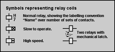
The drawing explains the various types of relay used in the system. "Battery" was a continuation of the Post Office telephone exchange practice of using a power source of 50 volts with the positive connected to earth. So Battery is, in fact, -50 volts relative to earth.

