SIX-CHANNEL DRAMATIC CONTROL UNIT DC/4

The DC/4 unit has six programme input channels and incorporates cue light keys, D.C. return lights, channel engaged lamps, loudspeaker volume control and housephone jacks. (The DC/4 installed in Birmingham is not quite standard, the D.C. return lights being operated from the mains instead of from the 24 volt battery. The DC/2 unit differs from the standard DC/4 unit in respect of the omission of the D.C. return light circuits, while the cue light keys and loudspeaker control are mounted on a separate panel.)

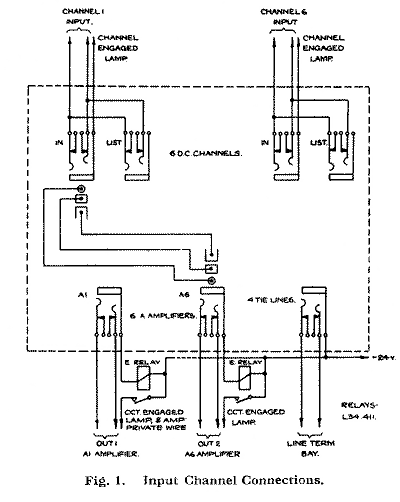
The No.1 outputs of the studio and echo 'A' amplifiers and of the 'D' amplifiers (the latter via tie-lines connecting with the Line Termination bay jackfield) are available on the Echo & D.C. jackfield for connection to the channel input jacks by means of double-ended cords as required.
Associated with each of the channels there is a fade control on the D.C. unit, and above each there is a channel engaged lamp provided with a socket into which can be fitted a lamp cap indicator marked to designate the programme source connected to the particular channel. The act of plugging up causes this channel engaged lamp to light via the sleeve circuit.
The E relay also operates, in series with the Channel engaged lamp, and connects -24 volt to the private wire of the 'A' or 'D' amplifier associated with the source causing the amplifier L.T. relay to operate, and to the circuit engaged lamp over the corresponding punching key on the S.B. & Operating position causing the lamp to light.
However, the amplifier should always be switched on manually so as to ensure that it will not be affected if the channel engaged lamp should fail.

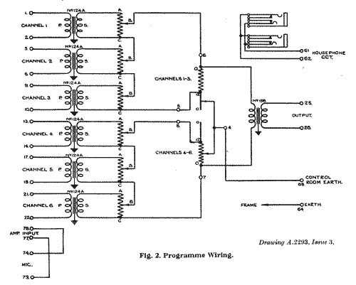
The talking-back microphone is permanently wired to terminals 73 and 74 and terminals 77 and 78 are connected to the input of the spare 'A' amplifier, the output of which is connected to the make contacts of the CO relay (Figure 3).
At certain stations the input and output of the spare 'A' amplifier are permanently wired via break jacks to the D.C. talking-back circuit, while at others the microphone output and the contacts of the CO relay are wired to jacks on the 'A' amplifier bay and the input and output of the spare 'A' amplifier must be plugged up to them.
The amplifier can be switched on by means of the key on the amplifier bay, but at some stations a switch for the purpose is fitted on the D.C. unit.
Figure 2 also shows the D.C. housephone circuit jacks the outers of which are wired to the outers of the LS & HP Input jack in the Loudspeaker jackfield (Figure 3).
Loudspeaker Switching
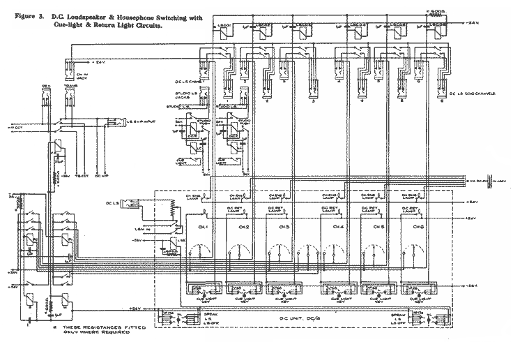
The loudspeaker connections are performed by means of plugging operations on the Housephone & Loudspeaker jackfield and can be followed by reference to Figure 3 (above, or click on the image for a larger version in a new browser tab).
The Studio LS jacks of the individual studios must be plugged up to the DC. LS Chan jacks to correspond with the plugging up of the studio outputs to the D.C. input channels on the Echo and D.C. jackfield. The LS & HP Input jack and the DC. LS Input jack must be plugged up to the TV. LS Output jack of the trap valve amplifier connected in the output of the 'B' amplifier to which the D.C. output is connected. The CH. In jack must be connected, in the case of a transmission, to the Trans jack and, in the case of a rehearsal, to the Reh jack. Where echo is being used on one of the programme sources, connection must also be made between the DC. LS Echo Chan jack of the channel to which the programme source is connected and the DC. LS Chan jack of the channel to which the echo 'A' amplifier output is connected.
The outers of the DC. LS Chan jacks, to which the Studio LS jacks are plugged up, are connected each to the travellers of an LS. CO relay associated with the particular channel. The make contacts of this relay are connected, via the inners of the associated DC. LS Echo Chan jack, to the outers of the CH. In jack , which is connected via the Trans or Reh jack, as the case may be, and the LS & HP Input jack to the trap valve loudspeaker output. Thus, when the particular LS. CO relay operates the studio loudspeaker is connected to the output of the trap valve amplifier.
One side of the winding of all the LS. CO relays is connected to -24 volts. The other side of the winding is connected to a switch on the associated channel fade control and also to one of the back contacts of the P relay associated with the group to which the channel belongs. When the particular channel is faded out (through 0 to LS) the switch closes and applies +24 volts to the winding of the associated LS. CO relay, which operates giving the particular studio its loudspeaker. When the central mixer is turned to either of its extreme positions, +24 volts is applied via an auxiliary slider to the winding of the P relay associated with the group of channels faded out. The relay operates closing its three contacts and causing the LS. CO relays connected to them to operate, thereby connecting the loudspeaker in the associated studios. These arrangements ensure that the loudspeaker will not be in operation in any studio while the channel to which its microphone is connected, is faded up.
But for the DC. LS Echo Chan jack connection, it would be possible, when echo is being used on any studio, for the producer to cause the whole system to howl if he omitted to fade out the echo channel at the same time as he faded out the direct programme source; for, as soon as the studio channel was faded out the loudspeaker in that studio would be brought into circuit, while, seeing that the echo channel was not faded out, the microphone in the same studio would be connected, via the No.2 output of its 'A' amplifier and the echo room, to the loudspeaker input. To obviate this condition connection is made, as previously stated, between the DC. LS Echo Chan jack of the channel to which the studio is connected and the DC. LS Chan jack of the channel to which the echo output is connected.
For example, suppose the studio output is connected to channel 5 and the echo on this studio to channel 6, then the studio loudspeaker input is connected to the DC. LS Chan 5 jack and the DC. LS Chan 6 jack is connected to the DC. LS Echo Chan 5 jack. The inners of this last jack are disconnected by the act of plugging in. Consequently the studio loudspeaker input will only be connected across the CR. In jack, (via the inners of the DC. LS Echo Chan 6 jack ) when both the LS CO. 5 and LS. CO 6 relays have operated. This means that the studio only gets its loudspeaker when both the direct and echo channels have been faded out or, of course, if the group comprising channels 4, 5 and 6 has been faded out on the central mixer.
Talking-Back Circuits
The rehearsal talking-back arrangements differ from those for transmission. In the former case the production can be held up for the purpose and the studio loudspeakers can therefore be used. But in the case of a transmission the operation of the talking-back circuit obviously must not be allowed to interrupt the performance, and so the housephone circuits are used.
The input circuit of the loudspeaker in the D.C. room is connected to the travellers of the LSS relay. When the talking-back key on the panel is in the central (or LS) position, the back contacts of this relay are made and the LSM connected across the output of the loudspeaker control potentiometer on the panel. Operation of the talking-back key to either its LS Off or Speak position applies +24 volts to the winding of the LSS relay, which operates and disconnects the D.C. loudspeaker.
For a transmission, connection is made, as previously stated, between the CH In and Trans jacks. Where necessary, the spare 'A' amplifier must be plugged up, by means of jacks provided on the 'A' amplifier bay jackfield, to the talking-back circuit, the amplifier input being connected to the output of the talking-back microphone and the amplifier output to the talking-back relay switching circuit. The housephone inputs of the studios to be used must be plugged up to the strip of parallel jacks in the Loudspeaker & Housephone jackfield, wired to the D.C. housephone switching circuit.
The Trans jack is connected, in parallel with the LS & HP Input jack, to which the TV. LS output is plugged up, to the back contacts of the CO relay. The studio housephone input circuit is connected to the travellers of this relay. The output of the spare 'A' amplifier, used with the talking-back microphone is connected to its front contacts. When the talkingback key is held in the Speak position, relay S operates, completing a circuit for the operation of the CO relay, which transfers the housephone circuit connection from the trap valve output to the talking-back amplifier output.
For a rehearsal, the CH In and Reh jacks are plugged up to one another and, where necessary, the input and output connections of the spare 'A' amplifier completed as before.
When the talking-back key is held in the Speak position the M relay operates over the sleeve circuit. This relay completes the operating circuit of both P relays, thereby causing all of the LS. CO relays to operate and all the studio loudspeakers to be connected in parallel, via the CH In and Reh jacks, across the travellers of the CO relay. As before, the operation of the S relay completes a circuit for the operation of the CO relay and transfers the loudspeaker and housephone connection from the TV. LS output to the output of the talkingback 'A' amplifier.
Release of the talking-back key restores the original condition of the circuits, but if the CO and LSS relays were allowed to release first there would be a momentary howl. A 25µF. condenser, sometimes in series with a 600Ω resistance, is, therefore, shunted across the windings of the CO and LSS relays in order to delay their release sufficiently to allow the P and LS. CO relays to restore first.
Cue Light and Return Circuits
The cue and return light circuits are shown only in the case of the loudspeaker circuits connected to channels 1 and 2, although similar equipment is provided for all the studio loudspeaker circuits.
The operation of the cue light key associated with a particular channel connects -24 volts, which is standing on the make contact of the key, via the sleeve circuit of the associated DC. LS Chan and Studio LS jacks, and the normally-made back contact of the DCR relay, to one side of the winding of the LC relay, on the other side of which +24 volts is standing. The LC relay, therefore , operates, closing the mains circuit which lights the cue light in the studio.
The studio can signal back to the D.C. position by means of the return light circuit. Operation of the studio push provides a circuit for the operation of the DCR relay. This connects -24 volts via the sleeve circuit of the Studio LS and DC. LS Chan jacks and the contacts of the key (in the unoperated position) to one side of the associated D.C. return lamp, which lights.
Summary of Connections for D.C. Working
Programme Connections (Echo & D.C. Jackfield)
For direct programme sources, double-end between D.C. Chan inputs and the 'A' or 'D' amplifier No.1 outputs, in accordance with the grouping requirements for the particular production.
For echo sources, double-end between the 'A' or 'D' amplifier No.2 outputs and separate echo inputs, and double-end between the associated echo 'A' outputs and D.C. Chan inputs, according to the grouping requirements for the particular production.
On the panel insert lamp caps for the channel engaged lamps designated to correspond with the programme connections set up.
Loudspeaker and Housephone Connections (Loudspeaker & Housephone Jackfield)
Double-end between the Studio LS Input and DC. LS Chan jacks to correspond with the direct programme input connections. Where echo is used, double-end between the DC. LS Chan jack of the channel to which the echo source is connected and the DC. LS Echo Chan jack of the channel to which the direct programme source is connected.
Double-end from the Trap Valve LS Output to the DC. LS Input and LS & HP Input jacks.
For a transmission, double-end between CH. In and Trans and between the Studio HP inputs and the D.C. HP parallel jacks.
For a rehearsal, double-end between CH. In and Reh.
Talking-back Microphone ('A' Amplifier Bay)
At stations where the spare 'A' amplifier is not permanently wired to the D.C. talking back circuit, double-end between the talking-back microphone output and the spare 'A' amplifier apparatus input, and between the D.C. talking-back circuit input and the spare 'A' amplifier apparatus output.
Control and Signalling Connections
Switch on the 'A' or 'D,' 'A,' Echo 'A,' trap valve, and DCA amplifiers by means of the manually operated keys on the amplifier bays. For a transmission, punch up the 'C' amplifiers of the lines to which the programme is to be sent to the output of the 'B' amplifier, and punch up its input to the DC output. For signalling the studios, operate the DC Con key and then the signalling keys of the various studios required. Finally operate the DC key when the programme is faded up.


