In 1962 when these photos were taken, there were four continuity
suites identical in facilities, panel layout and in the relative positioning
of the cubicle and studio desk. Con 1 was used for the Home Service, Con 2
for the Light Programme and Con 3 for Network 3 and the Third Programme. Except
for Con 4, shown in these pictures, all had some daylight so naturally Con
4 was treated as the spare. It was suggested during the planning and construction
stages that Con 4 could be used as a production mixer suite, but as far as
I know this was never implemented, probably because it was realised that when
it was in use as a mixer there would no spare con should a fault occur in
one of the other three.
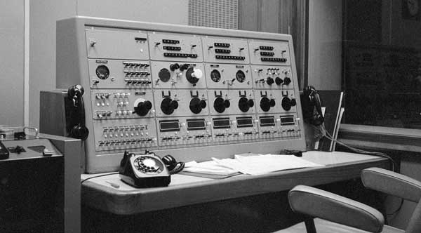
Leaving aside the left hand column of panels for the moment, there were six
channels handling remote sources. The three panels of push buttons and six
select keys at the top allowed any one of 200 sources to be selected to each
channel, although not all of these were relevant to the work of continuity.
It would have been perfectly possible to have one set of push buttons and
six select keys but the system used had built-in redundancy to allow for mechanical
failure of the push buttons. In practice, though, they were extremely reliable.
The third row of panels carry the faders and red light signal keys for the
six channels.
Below these faders are the indicator windows to show what source has been
selected to a channel together with adjacent 'pre-fade listen' keys ('pre-hear'
is the name now more commonly used). Beneath the indicator windows are four
keys and a lamp. The lamp together with a common buzzer indicated a call from
the source that could be answered by the operator on one of two bus bars A
or B. A second key allowed the operator to ring the source or to recall EMX
(the Engineering Manual Exchange in the Control Room) should the source need
to speak to control room. The remaining two keys fed either clean feed or
cue programme to the source via its cue line or control line if these were
available; in fact this facility was rarely used.
Also on this bottom row of panels are keys to ring and answer EMX. There were
two EMX telephone lines whose function depended on whether the suite was working
as a continuity or as a production mixer. EMX1 appeared on SB EMX when the
suite was serving a network under the name of that network (Home, Light, Third).
When the suite was not serving a network EMX1 appeared on OB EMX under the
name of the Continuity (1, 2, 3, 4). EMX2 had no function when the suite was
serving a network but a control line could be plugged to it for special purposes
such as a control line from Light Con to Green Con in Bush House. When not
serving a network, EMX2 was the control line associated with the suite in
the source multiple just like any other studio. The remaining two keys are
the operator's answer key switchable to the A or B bus bar and a similar key
to switch the announcer's telephone to either bus bar. Thus the operator and
announcer could hold separate conversations with two different sources or
both could have a 'conference' call to one or a number of sources. These comprehensive
arrangements were clearly intended for 'production mixer' use; routine con
operation made little or no use of them.

Moving back to the second row of panels and starting with the second from
the left, there is an STC 4021 'apple and biscuit' mic which was used for
talkback to the studio and for the technical intercom. The large white knob
was the main gain control with a pull type bypass switch below it that replaced
the control with an 18dB pad. The two small black knobs were pre-set level
controls on the mic and the gram outputs from the studio with a studio prefade
key between them. The next panel to the right carried the main and prefade
PPMs both of which could be 'slugged' by toggle switches at their upper right.
At their lower right is the electrical zero adjustment control. The two keys
were an LS dim key and Desk out/Check Receiver + PFL/Check Receiver. The last
panel to the right carries the check receiver indicators and a key which would
lock the output to either the AM or FM receiver as opposed to the normal sequential
20 seconds each switching. AM monitoring was eventually officially abandoned
as the quality change from FM was so disturbing. This panel also carried the
amplifier changeover pull switches and the announcer's main gain control bypass
pull switch together with lamps to indicate announcer's Mic On, Fader Up,
Fader in circuit and Rehearsal. The auto GTS (Greenwich Time Signal - the
"pips") key and indicator lamps were on the extreme right but the lamps were
a bit too small to warn the operator if the automatic system had selected
a GTS that was not required. The three black knobs from left to right were
the loudspeaker volume control, a cubicle ring main selector whose output
could be heard by operating the key to its right and a cue programme selector
for feeding cue programme to the cue and control lines. The three keys to
the left of the selectors were a Tone Key, Channel 6 signalling transfer which
transferred red light signalling on channel six to the announcer which I doubt
was ever used and a key to enable or cut talkback from the announcer to all
clean feeds. It is extraordinary that the operator had no means whatsoever
of using talkback to the cue or control lines although he could talk on the
telephone handset to a control line.
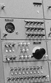
Returning to the first column of panels. At the top were the single Transmitter
Repeat Lamps. This facility is described in the section about the announcer's
desk. The locking key is for the continuity interchange system. If a network
needed to change to another con, both faded up the same programme and did
a PPM check. Then both operated their con interchange enable keys. In the
control room, the operator on the SB position checked that the spare con did
have the same prog on its output and then operated the key that switched it
into network. Nothing actually happened until the key for the con to be vacated
was operated up. When this was done everything was transferred to the spare
con - check receivers, C/R intercom, indicators outside the con doors and
in PABX etc, etc. There was no danger of howl round as the relays involved
were arranged so that it was impossible for one to operate before the other
had released and in addition they were mechanically latched by a bowed spring
so that they did not depend on the 50v supply to stay operated. After the
interchange had been done both cons released their keys.
The other three panels were mainly intended for an auxiliary operator although
Continuity soon became a one-man job (nobody spoke of one-person jobs in the
1960s). The auxiliary operator had a PPM fed by aux. prefade keys. The key
to the left of the PPM fed the aux. ops headphones with Desk Out or Check
Rx + PFL. The 15 keys to the right were the technical intercom. The speak/listen/off
key was to the left of the adjacent mic.
The third panel carried the tape fader with its bypass pull switch and, on
the left, the locking keys controlling the tape machines. With the keys as
shown in the picture, machines 1 and 2 are selected to the repro busbar and
machine 1 is started on remote. Only two machines could be selected to the
repro bus at a time. The first two that were selected locked out selection
of the third. The keys in the middle of this panel were aux. prefade. The
bottom panel gave the auxiliary operator access to all the telephone facilities
available to the main operator but with the addition of a means of sending
TIM (the speaking clock) to any control line for time checks.
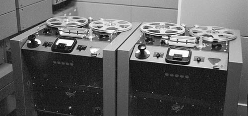
It was intended that the continuities would be equipped with EMI TR/90 tape
machines but they entered service with Leevers-Rich machines. These were later
replaced with Studer C37s.


