Related Page
MARK 1
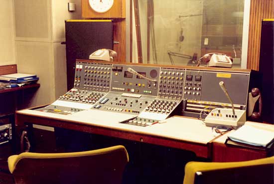
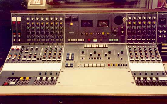
The 4 modules at the far left are outside source cue send modules. The red button diverts the output to the jackfield for use with a cue line rather than a control line. The modules in the upstand are for channel gain and EQ and the channel routing modules are below with group/ind routing, 2 aux bus bars, echo and a (red) pan pot above locking PFL/AFL buttons.
To the left of the main PPMs are repeat "limiting db" meters for the com/limiters which are themselves located out of eye line away to the right. Below are tone send buttons, local red light, transmission/rehearsal and buzz back buttons and (green) power supply indicators. The prominently placed blue and white buttons to the left of the main monitoring panel are for telephone ring and answer. Tape remote starts are just above the script space. Talkback keys are Master, Studio, Aux, Slate and 4 Outside Sources.
It might not be perfect but it's strange to think that, before a bit of rebuilding work, there was a Marconi desk here.
THE TCC
The SM members of the Technical Consultative Committee enthusiastically set to work on the layout of a new desk to be known as the GP Mark 3. The new desk would have script space in front of the faders, a lower profile and redesigned EQ, monitoring and OS cue modules. Unfortunately there was not much effort available to turn these ideas into drawings to take to a manufacturer and time was running out for the many Type B desks around BH and especially so for S1 which was still Type A. So work on the new desk was delayed and a compromise desk was devised using the existing carcase and modules apart from a much improved OS cue module. This became the GP Mark 4.
MARK 4
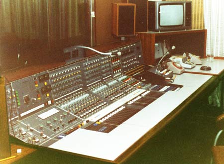
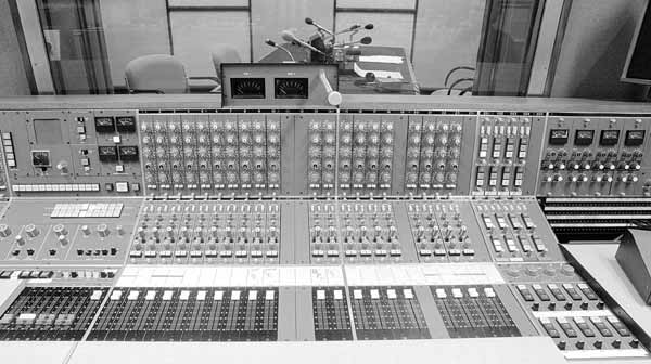
3C, above, was the first GP Mk 4 to appear and was well received but clearly illustrates one of the problems with GP. While SMs tended to think of it as a "pick and mix" system, it was very difficult and expensive to keep altering the drawings, so it had to be a standard size carcase with standard wiring. It was just as difficult to remove facilities as add new ones. 3C didn't need 24 channels, so some of the modules were kept as maintainance spares. They were later added as the desk looked odd without them. Note that the PPM pod has been kept as low as possible by cutting away the surounding woodwork.
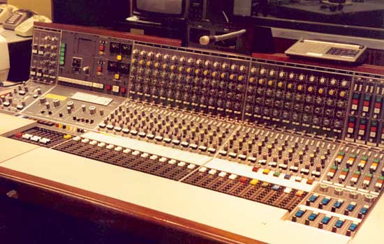
B15, as the main phone-in studio, normally used the last 6 outside source channels for telephone balance units and the indicator lights above the faders are non standard.
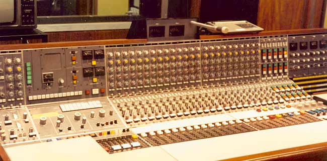
The left hand wing of the desk starts with main controls for the aux bus bars, group amplfiers and echo controls. Then comes the monitoring panel with tape remote starts and talkback keys below. The cluster of talkback keys includes 3 auxilaries. AUX 1 has been retained as a totally independent talkback, whilst AUX 2 and 3 are intended for use by presenters and are mastered by studio talkback.
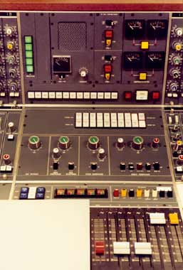
To the right is a closer look at a Mark 4 monitoring panel, this one actually is from 5A.
The two rows of white buttons at the top are mono and stereo monitoring selectors, the mono one includes Prefade and Aux outputs, whilst the stereo one has main and group outputs and is used for monitoring off-tape record feeds. (It was normal practice when recording programmes to monitor, or at least spot check, the delayed feed coming from the record machine playback head.)
The main monitoring controls are on the right with volume and balance controls either side of a programme ring main switch, followed by studio and auxilary controls.
MARKS 3 AND 3A
Broadcasting House began to fill up with GP Mk 4 desks and they proved their worth in studios as different as 3C (by now used for WATO/PM transmission because building work had started in the 3B area) and S2, a large studio often used for Schools music programmes.
It became clear that the brand new lower profile Mark 3 desk would now be limited to four "mixer" studios requiring a TO position to handle outside sources. After much anguish it was decided to stick with a proven design and make the Mark 3 as a mixer version of the Mark 4. Apart from the cost implications, one of the most telling reasons for sticking with the same design was that, at that time, most SMs worked across a wide range of studios. The number of controls had greatly increased, compared to Type B and at the same time radio had speeded up, so to be able to grab the same control in the same place in different studios was a great advantage.
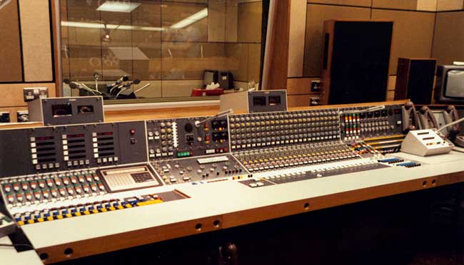
3B was one of two Mark 3A desks with 24 channels - 10 local, 2 dedicated phone channels and 10 outside sources. The other Mk 3A later went into 4A. There were two Mark 3 desks with 32 channels (20 outside sources) in B9 and 4C. Apart from the ability to transfer the SMs outside talkback working to a headset, there were few changes from the Mark 4.
The Technical Operators position is on the left with outside source selection and cue modules. For everyday use when this position was not staffed, 4 of the cue modules are duplicated to the right of the faders. Here too are cue modules for the dedicated telephone channels and a switch-down panel to select telephone balance units. Note that the "Tone to Clean Feed" buttons have now gone.
The studio was in the location of the original H30 and on the opposite side of the cubicle in the space occupied by the original 3B studio was 3K. This was designed as a back up/preparation studio to 3B and had a 12 channel GP desk with access to all 3B's outside sources without reference to control room. Originally it was designed for one SM operation with tape machines either side of the desk. This required a different method of working from anywhere else and was not a success. 3K was quickly changed to the conventional arrangement.
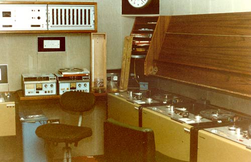
The large box on the wall is a Tape Control Panel. This is an elaborate way of routing all repro sources to a number of bus bars or individually in mono or stereo. Another panel out of shot carries record input selectors.
