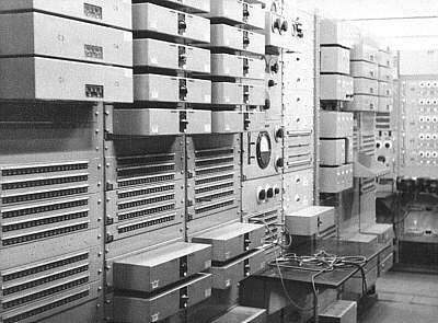
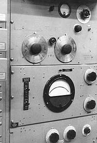
Above left: Some of the incoming and outgoing line amplifiers. Near the centre of the picture is the AC Test Bay, seen in detail on the right.
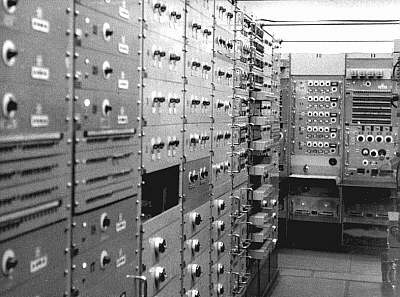
Left: Distribution amplifiers ('Trap Valves') with
their power supplies below them. This type of amplifier was succeeded by
C/9s.
Below left are the equaliser trays of the Greenwich Time Signal lines. The 'pips' actually came from Herstmonceux in Sussex. The signal sent was a continuous tone with 6 gaps every 15 mins. This was 'inverted' into 6 pips at BH. This arrangement made it easier to detect a line failure. Below right: GPA/4A amps looking a little out of place among the much older gear seen in other pictures.
Below left are the equaliser trays of the Greenwich Time Signal lines. The 'pips' actually came from Herstmonceux in Sussex. The signal sent was a continuous tone with 6 gaps every 15 mins. This was 'inverted' into 6 pips at BH. This arrangement made it easier to detect a line failure. Below right: GPA/4A amps looking a little out of place among the much older gear seen in other pictures.
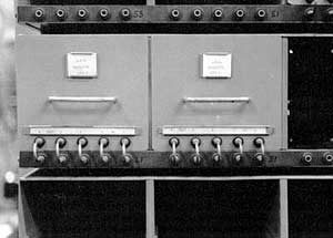
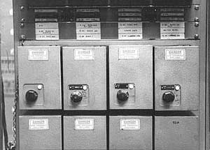
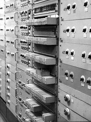
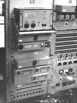
Left: relays and more trap valves. Right: check receivers with the control room Tannoy intercom amp at the top of the bay.
